
In this tutorial, we are going to learn how we can interface Soil Moisture Sensor with Arduino. Interfacing Soil Moisture Sensor can be used in variety of projects where we need to measure the value of water content or moisture in the soil i.e. in smart green houses.
In this tutorial, we are going to build a simple project in which different indicator LEDs turn ON depending upon the soil moisture present in the soil.
Components Required
- Arduino UNO
- Soil Moisture Sensor
- Breadboard
- Connecting Wires
What is Soil Moisture Sensor
Soil Moisture sensor is used to measure the water content or moisture present in the soil. It consists of two conducting probes attached with a circuitry board. It is actually a variable resistor, whose resistance gets changed when there is moisture on it’s two plates. The resistance between it’s conducting probes is inversely proportional to the water content or moisture in the soil. i.e. if there is more water in the soil, the resistance of conducting probes decreases and vice versa.
The working principle of the Soil Moisture Sensor is based on the Conductivity. The probes becomes good conductor when there is water content in the soil then when there is small water content in the soil.
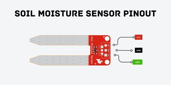
Sensor Pinout
Soil Moisture Sensor have 3 Pins.
- VCC – It supplies the power to the sensor. It is recommended to power the sensor from 3.3V to 5V.
- GND – It is the Ground Pin.
- SIG – Analog Output of the sensor.
Circuit Schematic
In this project, One Analog Pin of Arduino is used for the sensor and 5 Digital Arduino Pins are used for the indicator LEDs.
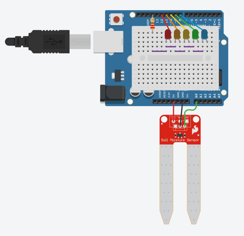
- The Signal Pin (SIG) of the sensor is connected with the Arduino A0 Pin.
- The +v terminal of the Red LED is connected with the Digital Pin 12 of Arduino.
- The +v terminal of the Red Orange is connected with the Digital Pin 11 of Arduino.
- The +v terminal of the Yellow LED is connected with the Digital Pin 10 of Arduino.
- The +v terminal of the Green LED is connected with the Digital Pin 09 of Arduino.
- The +v terminal of the Blue LED is connected with the Digital Pin 08 of Arduino.
- The -ve terminal of all the LEDs is connected with the GND via 220 ohm resistor.
Calculation
The output value of the sensor’s signal pin depends upon the voltage applied to the sensor. As the Output of the sensor is analog and connected to the Analog Pin of the Arduino, so here we need to do some calculation to convert that Analog value into Digital value. On the base of that value we can define the levels for the different LEDs. Analog to Digital conversion is very simple. The formula is below
Analog Output = (Input Voltage / Maximum Voltage) * 1024
After applying 5V to the sensor the maximum output voltages we are having is 4.28V so upon doing the above calculation we can see that the maximum value we can have from the output of sensor is 876.
Analog Output = (4.28/5) * 1024
Which means the Output of the sensor in the digital form we is from 0 – 876.
Now we need to define some values for the specific LEDs to turn on i.e. if the value of the sensor is between some specific value then the Red LED should turn ON and so on.
- If analog value from sensor is between 0-200, Red LED should Turn ON.
- If analog value from sensor is between 200-400, Orange LED should Turn ON.
- If analog value from sensor is between 400-600, Yellow LED should Turn ON.
- If analog value from sensor is between 600-800, Green LED should Turn ON.
- If analog value from sensor is between 800-876, Blue LED should Turn ON.
int moisture = 0;

void setup()
{
  pinMode(A0, INPUT);
  Serial.begin(9600);
  pinMode(8, OUTPUT);
  pinMode(9, OUTPUT);
  pinMode(10, OUTPUT);
  pinMode(11, OUTPUT);
  pinMode(12, OUTPUT);
}

void loop()
{
  delay(10); // Wait for 10 millisecond(s)
  moisture = analogRead(A0);
  // Print text in serial monitor
  Serial.println("Sensor Value:");
  // Print output voltage in serial monitor
  Serial.println(moisture);

  digitalWrite(8, LOW);
  digitalWrite(9, LOW);
  digitalWrite(10, LOW);
  digitalWrite(11, LOW);
  digitalWrite(12, LOW);
  if (moisture < 200) {
    digitalWrite(12, HIGH);
  } else {
    if (moisture < 400) {
      digitalWrite(11, HIGH);
    } else {
      if (moisture < 600) {
        digitalWrite(10, HIGH);
      } else {
        if (moisture < 800) {
          digitalWrite(9, HIGH);
        } else {
          digitalWrite(8, HIGH);
        }
      }
    }
  }
  delay(100); // Wait for 100 millisecond(s)
}
In the void setup(), we define the A0 Pin as Analog Input for the Sensor Signal Pin, and Pin 8, 9, 10, 11, 12 are defined as Digital OUTPUT for the LEDs. Also we Initialize the Serial output on the Serial Monitor of arduino using Serial.begin(9600).
In the void loop(), we simply store the Output of the sensor value in a variable named “moisture”. and printing out that value on the Arduino Serial Monitor.
After that all the LEDs are turned OFF and we define if else statements to Turn the LEDs ON and OFF based on the certain sensor value. On last there is a delay for 100 milliseconds.