In this tutorial, we are going to learn how we can connect an LED with Arduino and can control it.
Components Required
- 1 x Arduino UNO Board
- 1 x LED
- 1 x 220 ohm resistor
- Connecting Wires
- Breadboard
What is an LED
LED stands for Light emitting diode. It is a basic electronic component which emit lights when we connect it with the battery. It has two terminals one is Cathode (GND) and the other one is Anode (Positive).

How we can differentiate which terminal of an LED is Cathode or Anode?
If you see an LED, there will be two terminals one is Anode while the other is Cathode.
The bigger terminal of an LED is called Anode (+ve) while the smaller terminal of an LED is called Cathode (-ve).
In some cases, the LED have one straight terminal while the other one is tilted or bent terminal. In that case, the straight terminal is Cathode while the bent or tilted terminal is Anode.
When we connect the Cathode Terminal of an LED with GND of the Battery and the Anode Terminal of an LED with the Battery, it starts emitting light.
Connect the LED with Arduino
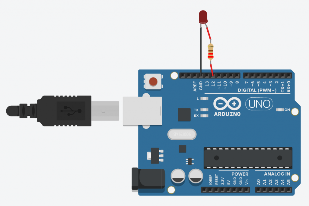
It is going to be a very simple circuit. All we need to do is to connect the LED’s Anode (+ve) terminal with the pin 12 or any other Digital Pin of Arduino via a 220 ohm resistor and connect the LED’s Cathode (-ve) terminal with the GND pin of Arduino.
Circuit Diagram
- LED’s Cathode = GND Pin of Arduino
- LED’s Anode = Pin 12 of Arduino
The circuit diagram is shown below.

Arduino Code
//
/*
  This program blinks an LED which is connected to the
  PIN 12 of Arduino
*/

void setup()
{
  pinMode(12, OUTPUT);
}

void loop()
{
  // turn the LED on (HIGH is the voltage level)
  digitalWrite(12, HIGH);
  delay(1000); // Wait for 1000 millisecond(s)
  // turn the LED off by making the voltage LOW
  digitalWrite(12, LOW);
  delay(1000); // Wait for 1000 millisecond(s)
}
The code is very simple. First of all we set the 12th Pin of Arduino to OUTPUT using pinMode function in void setup(). After that in void loop() we are setting the pin 12 of the Arduino to HIGH using digitalWrite function to make the LED turn ON then taking a delay of 1000 milliseconds and then setting the pin 12 of Arduino to LOW using digitalWrite function to turn it OFF and again 1000 milliseconds delay. This loop continues until the Arduino is Powered On and it will create a Blinking LED effect.
